
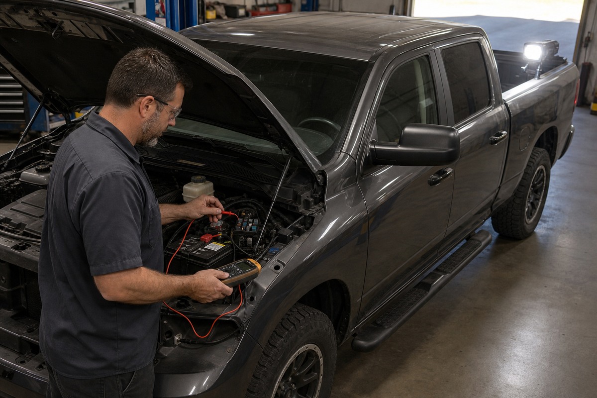
A bed light that dims when a compressor starts, a camera that reboots over rough pavement, or an auxiliary socket that works only with a light load can make a good accessory look defective. Before replacing the device, treat the failure as a circuit event: reproduce it, keep the accessory operating, and find where voltage is being lost.
The key is to test while current is flowing. Fluke’s automotive voltage-drop guidance explains that an unloaded resistance check can miss restrictions that appear only when a lamp, motor, relay, or other device is working. That makes an under-load measurement more useful than swapping parts until the symptom disappears.
Read the failure as a circuit event
Begin with the exact condition that triggers the problem. Note whether the engine is running, which other loads are on, whether the fault follows vibration, and whether more than one accessory changes at the same time. A single light that flickers may point toward its local connector or ground. Several accessories dropping out together make a shared feed, relay, fuse holder, or return path more important to inspect.
Do not probe an unfamiliar factory harness simply because it is nearby. Modern pickups may provide documented auxiliary switches, upfitter terminals, or designated grounding locations, and those provisions vary by model year and equipment. The Ram Body Builder’s Guide, for example, directs installers to model-specific technical and upfitter wiring information instead of a universal connection point. The same principle applies to Ford, GM, Toyota, and other trucks: identify the vehicle and the intended factory interface before diagnosing an added circuit.
Record the load, not just the symptom. Write down the accessory, switch position, engine state, and other active loads. Repeating the same condition after a repair is the only fair comparison.
Split the path into feed and return
A working accessory circuit has two sides: power travels from its protected source to the device, then returns through the ground path. Measure voltage drop across one section at a time while the accessory is switched on. A reading across a cable, connection, switch, relay contact, or ground point shows the voltage being used up by that section; measuring an inactive circuit does not reveal the same restriction.
- Loss appears on the feed side
- Inspect the fuse holder, relay contacts, crimped terminals, splices, and the wire run toward the accessory. Look for looseness, corrosion, heat discoloration, or a conductor that is too small for the documented load and length.
- Loss appears on the return side
- Inspect the accessory ground, the attachment surface, fastener condition, and any shared body or chassis connection. Paint, rust, sealant, or a loose terminal can restrict the return path even when the wire looks intact.
- Supply remains stable but the device stops
- Confirm the measurement at the device connector under the failing condition. If both feed and return remain within the vehicle and accessory maker’s specifications, the device, its control input, or its internal protection becomes a stronger suspect.
Use the truck and accessory documentation for acceptable limits and probe locations. Generic numbers are useful only as orientation; they do not replace a model-specific service procedure. If the circuit is connected through factory auxiliary switches, verify the correct output and configuration rather than moving the wire to an unrelated fuse position.
The fuse protects the circuit
A fuse is not a cure for a circuit that repeatedly overloads or shorts. The automotive section of the Littelfuse Fuseology guide describes a fuse as an overcurrent protection device for the circuit. Replacing a failed fuse with a larger value can leave the wire or connector exposed to more current than the circuit was designed to carry.
Match the documented fuse type and rating, then find why it opened. Inspect the holder for weak contact pressure and heat, confirm that the wire is protected near its source, and verify that every added branch has an appropriate protection plan. Do not bypass a fuse, bridge a relay, or borrow power from a safety-system or data circuit to make an accessory operate.
Routing matters as much as the electrical reading. GM Upfitter Integration’s electrical best practices call for added wiring to be secured against pinching, entrapment, and misrouting. On a pickup, that means keeping the loom away from exhaust heat, steering and suspension travel, sharp bed seams, cargo pinch points, and places where a tonneau-cover clamp or toolbox fastener can crush it.
This is especially relevant when adding wheel-well lighting or auxiliary lamps to a vehicle-specific front bar. The accessory location may be obvious, but its power source, fuse, grounding point, and protected route still have to match the vehicle.
Prove the repair with the same load
After repairing a confirmed connection or replacing damaged circuit hardware with the specified type, operate the same accessory under the same conditions recorded at the start. Repeat the feed-side and ground-side measurements. A lower drop, stable operation, and no new heat or odor provide stronger evidence than a quick no-load switch test.
Then inspect the physical installation once more. The loom should remain supported with the hood, tailgate, bed cover, and tool storage in their normal positions. Connectors should be fully seated and weather protection restored. Required exterior lamps, vehicle controls, and unrelated accessories should still behave normally.
If the correct factory interface cannot be identified, the circuit enters a control module, or the problem involves overheated insulation, repeated fuse failure, or an unknown high-current load, stop guessing. Preserve the evidence you recorded and use the vehicle wiring information or a qualified automotive electrical technician. The useful outcome is not merely making the accessory turn on; it is proving that the feed, protection, routing, and return path can support it under real load.